Glass-Weave Skew
Glass-weave skew (GWS), alternately known as the Fiber-weave effect (FWE) has become a pretty hot topic in high-speed digital design over the last 10 years. The phenomenon is caused by the need for near-complete symmetry between two halves of a differential pair, progressively-increasing bit rates, combined with the inhomogeneity of the cross-sectional environment around each half of the differential pair for glass-fabric-based laminates. It’s not quite as complicated as it sounds once you break down the problem into its parts, and then consider the potential solutions.
Articles and Resources:
Click here to download the Z-planner evaluation software and Glass-Weave Skew Tutorial.
Fill out the short form on the right to be e-mailed links to the following educational resources:
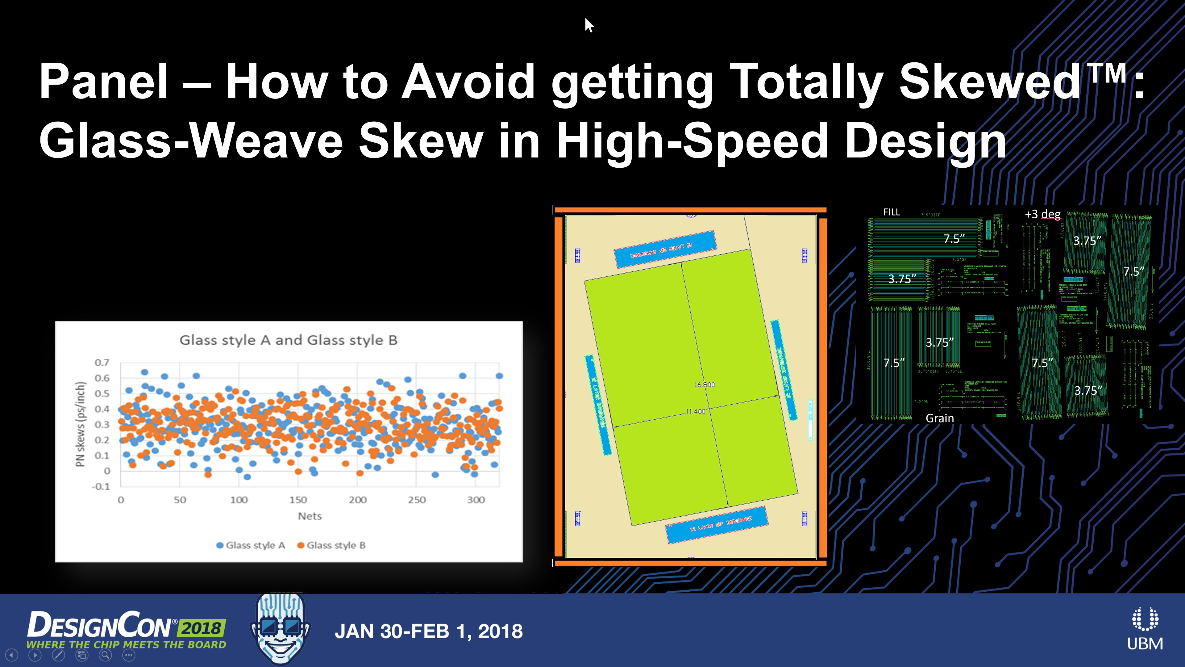
- Panel discussion: “How to Avoid being Totally Skewed,” DesignCon 2018, Bill Hargin, Lee Ritchey, Scott McMorrow, Stephen Scearce, Amendra Koul, and Dave Hoover
- “Impact of PCB Laminate Weave on Electrical Performance,” DesignCon, 2005, Scott McMorrow, et al
- “Skewering Skew—Laminate Weave Induces Skew,” Printed Circuit Design, April 2005, Eric Bogatin
- “Fiber Weave Effect: Practical Impact Analysis and Mitigating Strategies,” DesignCon 2007, Jeff Loyer, et al
- “A Way to Address the Problem of Jitter and Skew in Gigabit and Faster Signals Caused by Laminate Weaves,” Current Source, June 2007, Lee Ritchey
- “New Characterization Technique for Glass-Weave Skew,” DesignCon 2016 (Part 1)/2017 (Part 2), Eric Bogatin, Bill Hargin, et al
- “Vehicle for Insitu Glass Fabric Characterization,” EDI Con, 2017, Scott McMorrow and Brandon Gore
- “Glass Weave Skew Effect on 56Gbps PAM-4 System,” DesignCon 2018, Stephen Scearce, et al
- “Modeling, measurements, challenges and impact on differential insertion loss for weak- and strong-coupled lines,” DesignCon 2018, Amendra Koul, et al
[contact-form-7 id="2973" title="Glass-Weave Contact Form"]
What Causes Glass-Weave Skew?
A signal’s propagation velocity is inversely proportional to the square root of the effective, average dielectric constant (Dk) of the medium surrounding each half of the differential pair. Electrical-grade glass fabric has a Dk approaching 7.0, while most resins have Dk’s approaching 3.0. Combine the two in cores and prepregs, and the effective Dk of the material (i.e., the values reported by laminate manufacturers, as a function of resin content (%) and frequency) ends up being around 4.0. However, chances are pretty good that one of the differential signals will “see” more resin than the other half, so you end up with two different effective Dk’s and – as a result – two different average propagation velocities. The signal speed with more glass around it will be slower than the one with more resin. The resulting difference in total delay is referred to as “Glass-Weave Skew.”
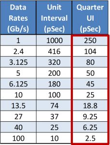
How much Glass-Weave Skew is too much? (Differential-Skew Tolerance)
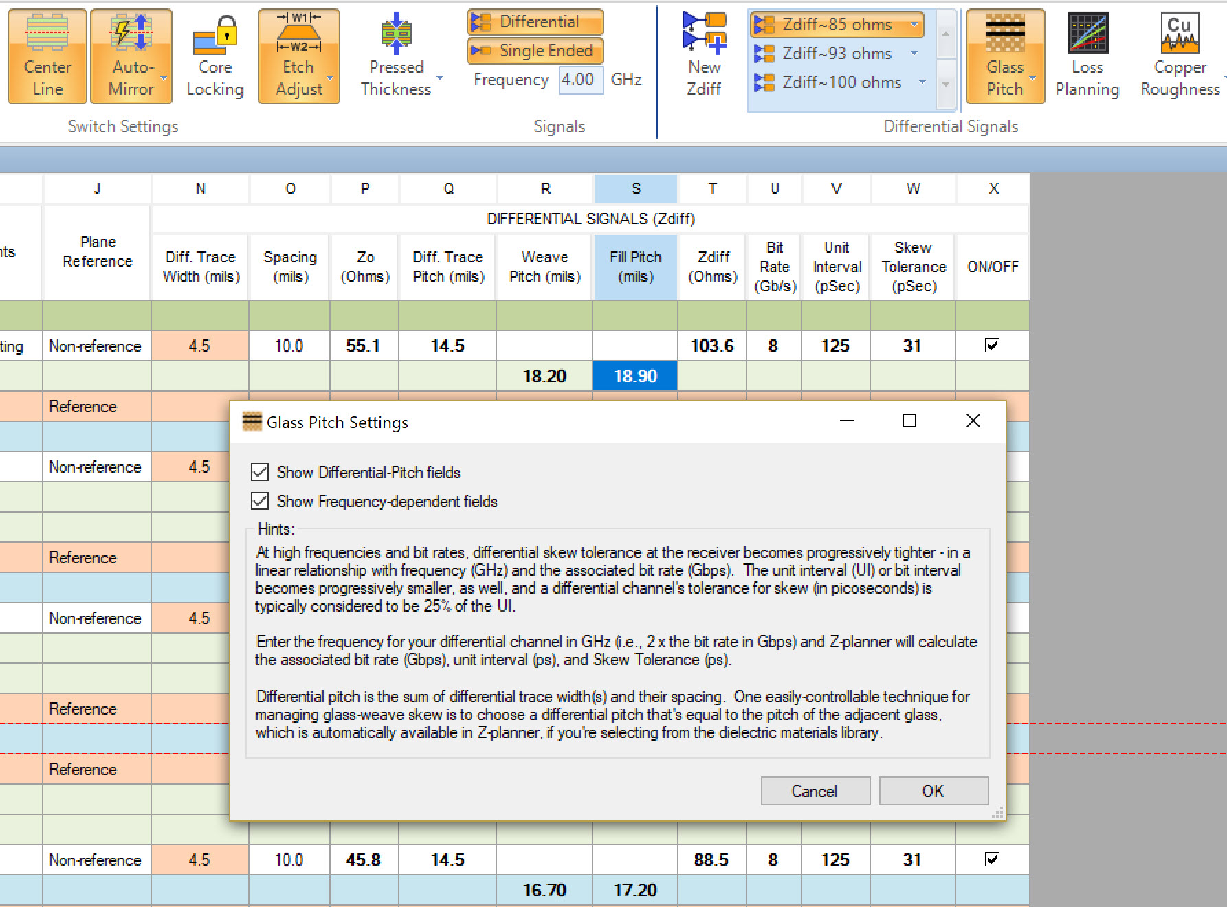
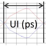
Differential skew, or simply “skew” is typically measured in picoseconds (ps). Each differential serial channel standard and speed has its own tolerance for skew. Most standards or chip manufacturers will offer their own guidance on skew tolerance, but we can generically characterize a channel’s tolerance for skew is described as roughly 25 percent of the bit stream’s unit interval (UI). For example, a 1 Gbps (500 MHz) signal would have a UI of 1000 ps. Using 25 percent as a guideline, that represents a 250 ps skew tolerance. That’s a pretty wide window, and that’s why most engineers didn’t need to worry about GWS around the turn of the 21st century. Fast forward to designing at 10 Gbps (5 GHz). The unit interval will be 100 ps and the skew tolerance will decrease proportionally, to around 25 ps. PCI Express 4.0’s signaling speed, at twice the speed of PCIe-3.0, is even faster, at 16 Gbps (8 GHz). This maps to roughly a 60 ps UI, and 15 ps of skew tolerance – half of the 30 ps skew tolerance in PCIe-3.0.
Predicting Glass-Weave Skew
Predicting Glass-Weave Skew is a tricky proposition. What is the chance that one line in a pair will see a different dielectric constant than the other? There are systematic parameters, like glass pitch, differential-trace pitch,
glass weave style, line length, fabric and resin Dk. But the actual GWS for a particular differential pair is also heavily dependent on the chance alignment of the glass bundles under the two lines. Because there’s a hard-to-predict, semi-random component, 95 percent (less or more …) may work fine, while the remaining boards are dropping bits. It’s a slippery problem.
Preventing Glass-Weave Skew
It would be nice if there was a simple, cost-free panacea for GWS, but almost all of the remedies represent partial solutions that may work at some frequencies and line lengths, but not for others. Here are some of the skew-control techniques that you may have heard about – roughly ranked in descending order of cost in manufacturing:
- Choose a glass style that minimizes resin windows
- Choose a glass style with a “square weave” (equal # of yarn strands in the weave and fill directions)
- Route each member of the pair at the same pitch as the glass fibers
- Align trace direction to the fill/weft
- Mechanically-spread glass
- Dual-ply glass
- Half weave pitch jog—halfway down the track
- Zigzag routing of differential pairs at a 10 º angle to the weave
- Build each PCB with the artwork rotated at a 10 º angle to the panel and weave
- Use glass with a lower dielectric constant (closer to the resin Dk)
It’s beyond the scope of this overview to elaborate upon the above simple descriptions, but the following points should be highlighted:
- You may want to combine several of these techniques—particularly 1-6.
- If you’re zigzagging the routing (8) or rotating your board artwork (9), these approaches should be sufficient, although both carry costs.
- You can also see significant reductions in skew with dual-ply (6), low-Dk glass (10, for example, but both of these approaches add to manufacturing cost. (Low Dk glass is roughly twice as expensive.)
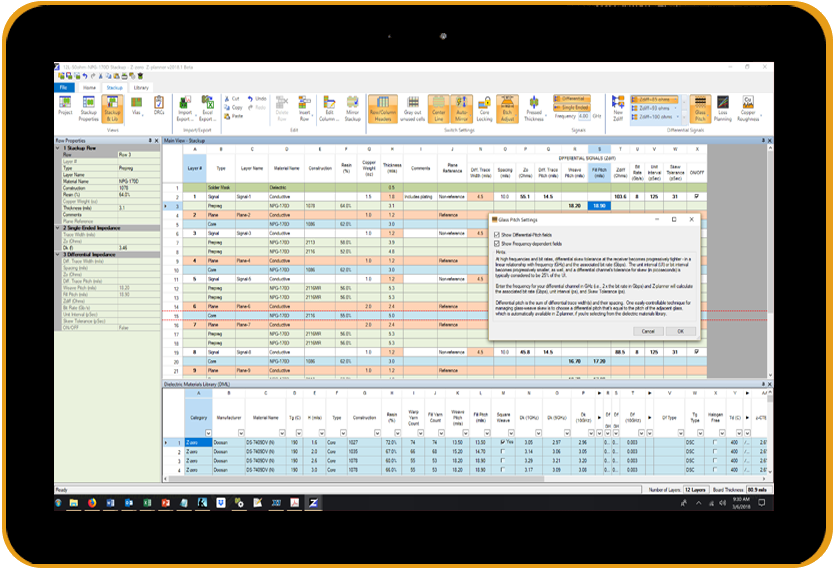
Z-zero’s patent-pending Z-planner stackup planning software can assist you with several of the “free” solutions noted above.

