An Ode to Pi
Understanding key differences between the time and frequency domains.
As March approaches each year, I can count on the bullfrogs around our neighbor’s pond to be out in force, memories of my baseball and softball coaching days as I walk by the ballfields, my wife’s birthday, and on March 14, “Pi Day,” which has been celebrated by geeks around the globe since 1988. I take the day seriously due to pi’s prevalence in almost every field of science, ranging from astronomy, electromagnetics, physics, to probably several other fields that I’m not even thinking about. How did pi find its way into so much science and what are the implications for electromagnetics?
The Unit Circle, Radians, and Angular Velocity
Before we go into details regarding the time and frequency domains, it’s beneficial to discuss the “unit circle” and radians. A unit circle is simply a circle with a radius of 1 (regardless of units). The circumference of a unit circle is 2π, meaning that one cycle would be 2π and that there would be 2 x 3.14 radians required to complete the circle. This is illustrated in FIGURE 1.
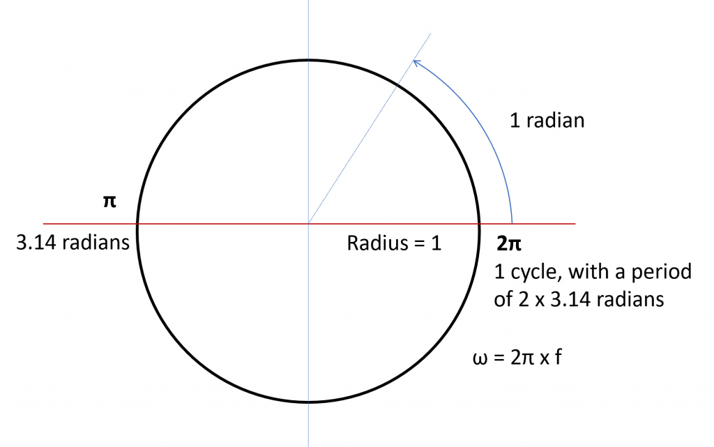
FIGURE 1. The unit circle has a radius of 1 and a circumference or period of 2π.
2π is the period or circumference of the unit circle. Without the mathematical relationships tied to the circle and to pi, it’d be very difficult for signal-integrity simulation software to model the behavior of signals without building circuit boards and making physical measurements. In other words, we’d only know what was going to happen after it already happened.
Angular frequency’s connection to electromagnetics is discussed further below. For now, just realize that the number of times we sweep through the period per unit time is the angular frequency, typically represented in radians per second.
Time and Frequency Domains
The Time Domain. We’re naturally more familiar with the time domain, which we deal with in everyday life; but the frequency domain can provide valuable insight into signal-integrity effects, impedance, and loss. To understand this connection, we need to discuss both the time and frequency domains. Dr. Eric Bogatin’s book, Signal and Power Integrity Simplified, does an excellent job of describing the differences and distinctions, so I’ll leverage that information, with his permission.
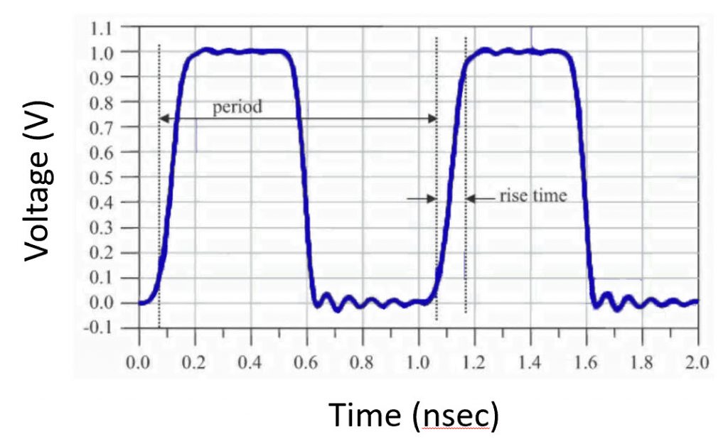
FIGURE 2. A clock signal, shown in the time domain, with a period of 1.0 ns. (Bogatin, Eric. Signal and Power Integrity – Simplified; Prentice Hall PTR Signal Integrity Library.
Using relationships that are well-known in the time domain, the clock frequency shown in FIGURE 2, Fclock represents the number of cycles per second the clock goes through, which is the inverse of the clock period, Tclock.
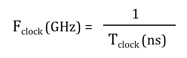
The math is easy if we represent frequency in gigahertz and the clock period in nanoseconds. The signal in FIGURE 2 has a frequency of 1 GHz. Similarly, a 10 GHz signal would have a period of 0.1 ns.
It’s important to note that the time domain is the only domain that’s real. What we describe as the “frequency domain” below connects the time domain to the title of this article.
The Frequency Domain. As mentioned above, the frequency domain provides valuable insight into signal-integrity effects, impedance, and loss. If you’ve been around hardware design for long, you’ve no doubt heard about the “frequency domain,” which is where pi really starts to appear. In Signal and Power Integrity Simplified, Dr. Bogatin points out, “The most important quality of the frequency domain is that it is not real. It is a mathematical construct. The only reality is the time domain. The frequency domain is a mathematical world where very specific rules are followed.” (Emphasis mine.) This is the part of the world where you can use “imaginary numbers” and people won’t think you’re crazy.
In the frequency domain, everything’s a sine wave and sine waves are everything. Any waveform in the time domain can be completely characterized by a combination of sine waves. And mathematically, we know all about sine waves.
Sine waves typically provide a straighter path to an answer because of the types of electrical problems we often encounter in signal integrity. Transmission lines, in a simplified sense, can be represented as networks of resistors (R), inductors (L), and capacitors (C). As Eric points out, if we “send any arbitrary waveform in, more often than not, we get waveforms out that look like sine waves and can more simply be described by a combination of a few sine waves.”
No new information is added when switching from the time domain to the frequency domain, but certain things, including but not limited to scattering parameters (S-parameters, a topic for a future column) live quite happily in the frequency domain. Results from an SI simulator can be viewed in either the frequency or the time domain. To illustrate the simplicity of the frequency domain, compare the plots in FIGURE 3.
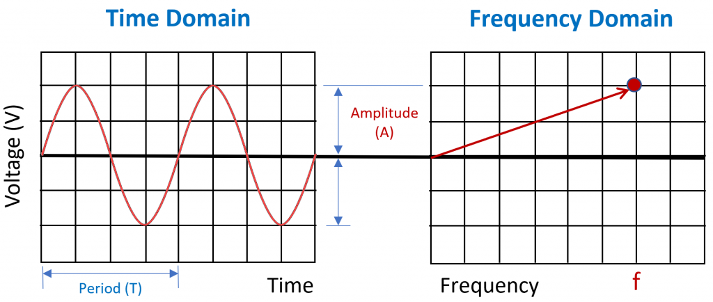
FIGURE 3. A sine wave, shown in the time domain, with hundreds of data points in the time domain, contrasted to representing the same sine wave in the frequency domain with just one data point, described as frequency (f) and amplitude (A). (Adapted from Bogatin, Eric. Signal and Power Integrity – Simplified; Prentice Hall PTR Signal Integrity Library.)
This is an excellent illustration of how much easier it is to describe things in the frequency domain. If the time-domain plot represents hundreds or thousands of datapoints, the same sine wave in the frequency domain can simply be described with a frequency (f) and amplitude (A).
“But what about pi?” you might asking. Well, sine waves have amplitudes, frequency (and periods), as well as phase. The frequency (f, measured in Hertz) is the number of complete cycles per second made by the sine wave. Angular frequency is measured in radians per second. As shown in Figure 1, radians describe fractions of a cycle. Figure 1 shows that there are 2 × π radians in one complete cycle. As a physicist-friend recently said, “We humans can devise other angular systems to our taste, like say 360 degrees, cause, hey, the number divides really well; but they are arbitrary. When we finally meet up with the guys from Zeta Reticuli they are unlikely to have 360 degree circles, but they will agree that a circle or cycle is 2π.” That’s because the ratio between the circumference of a circle to its radius will be the same in Euclidean spaces.
The Greek letter omega (ω) is typically used to refer to the angular frequency, measured in radians per second. The sine-wave frequency and the angular frequency are related by the following:
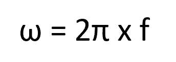
where ω is the angular frequency in radians/second and f is the sine-wave frequency in Hz. Once we’ve transformed the frequency into radians/second, the mathematical relationships of complex systems become much easier, as we will discuss further below. But rather than blowing past the relationship between angular frequency and your time-domain frequency, make sure that you’ve understood and memorized the relationship between angular frequency and time-domain frequency above, as ω is extremely prevalent in the frequency domain.
Impedance and Reactance
As mentioned above, transmission lines can be represented by a network of parasitic resistance (R), conductance (G), inductance (L), and capacitance (C). Each of these impedes current flow. We characterize these factors that impede current flow as follows:
- Resistance (R) is the impedance to current flow represented by an ideal resistor, in ohms. Resistance has no relationship to frequency.
- Reactance (designated by X) is also represented in ohms, is the impedance to current flow from an ideal inductor (L) or capacitor (C). Reactance depends on signal frequency, as noted in the relationships below.
- Impedance (designated by Z) is represented by the combination of resistance and reactance, making it a function of frequency through the reactance elements.
The impedance relationship is shown below:
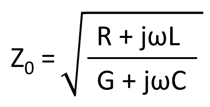
where G is conductance and R and G represent the “real” part of impedance, while the jωL and jωC represent the “imaginary” part of impedance—inductive and capacitive reactance in the frequency domain. Without going deep into what’s called “imaginary math,” the value of j is the square root of (-1). Obviously, the square root of (-1) doesn’t exist, hence the term “imaginary.”
Jenny, I’ve got your Number
I memorize pi as either 22/7 (simple enough) or 3.14159-ee-ine, rhyming with the Tommy Tutones song, “Jenny.” If you don’t know the song, I recommend getting out more and Googling it … It’s a cool song!
We could go much further here to discuss conductor loss and dielectric loss in the frequency domain, as well. Again, angular frequency, pi, and imaginary arithmetic are involved. I’m running long here, so I’ll save that discussion for another day, and will simply close by wishing everyone a happy Pi Day, if you celebrate!
References
Bogatin, Eric. “Signal and Power Integrity – Simplified,” Prentice Hall PTR Signal Integrity Library. Pearson Education.
Bogatin, Eric, DeGroot, Don, Warwick, Colin, Gupta, Sanjeev, “Frequency Dependent Material Properties,” DesignCon 2010, Santa Clara, CA.
Brooks, Douglas, “Signal Integrity Issues and Printed Circuit Board Design,” Prentice Hall Modern Semiconductor Design Series, 2003.
Interesting article that reminds me of middle school days learned pi for the first time.
Thank you!
Thanks WonSuk, Happy PiDay!
One fascinating “Eureka” moment (or me) was the sudden realization (not until 3rd year EEng) is this one “explanation” of this mysterious thing called a RADIAN !
My realization was that a RADIAN is “the LENGTH of a RADIUS”, (bent around the circumference),
Now I’m not sure what I can do with this but I found it quite intriguing. . .
I found this helps the primitive visualization, and all the unit circle diagrams continue to make sense, (in my experience “more” sense)
(for me) – typo in previous comment