Material Selection for High-Speed PCB Design, Part 2
How to develop a standard methodology, including electrical and mechanical parameters and – yes! – cost.
Au: This article is a comprehensive follow-up to the April 2019 Material Matters column in PCD&F. They may be read together or independently.
In April’s column, we discussed how total board thickness can be used to drive decisions on the appropriate glass-transition temperature (Tg) for the resin system. The thicker the board design, the higher the target glass-transition temperature. We also discussed material selection based on electrical properties, particularly a laminate’s dissipation factor (Df). We will go into more detail on both subjects here.
We start with IPC-4101 and the commodity myth. When it comes to purchasing circuit boards, the title “commodity manager” may have been reasonable 40 years ago in a world filled with double-sided boards, but it’s not accurate in today’s environment. If PCB materials and circuit boards are commodities, they’re among the most differentiated commodities I’m aware of, particularly when one considers “everything matters” at higher speeds.
The complexities incorporated into IPC-4101, Base Materials for Rigid and Multilayer Printed Boards, provide a great example of the breadth of options in the laminate space. Some of the property classifications – 64 different keyword-searchable “slash sheets” – include low-halogen content, filler content, glass type, high-thermal performance, high-speed/high-frequency performance, and thermal conductivity, along with the parameters noted below and more.
When winnowing the big list of laminate options, I use five or six criteria most frequently when comparing them:
- Dielectric constant (Dk)
- Dissipation factor or loss tangent (Df)
- Glass transition temperature (Tg, °C)
- Decomposition temperature (Td, °C)
- Total z-axis expansion (%), 50°-260°C
- X-y coefficient of thermal expansion (x-y-CTE, ppm/°C).
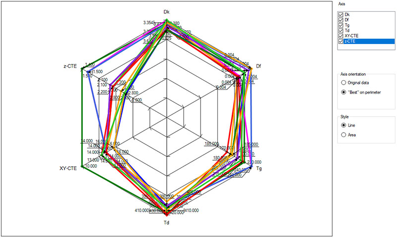
FIGURE 1 shows all six of the aforementioned parameters, comparing a handful of electrically similar laminates, with Dks and Dfs within 10% of one another. It’s a detailed list, but some differentiation emerges. The material in green shows a high degree of thermal stability (z-axis expansion and x-y-CTE). If those parameters are important – as discussed below – that material may be of interest. If x-y-CTE isn’t a huge concern, the blue plot shows promise on several parameters.
Here we’ll discuss what these characteristics are and why they’re important. Several important parameters are intentionally being withheld from this discussion:
- Whether a material meets UL halogen-free requirements
- Several mechanical details, including things like water absorption, peel strength, Poisson’s ratio, Young’s modulus, etc.
- Detailed reliability testing on actual test vehicles
- Detailed pricing.
This is not to imply these aren’t important. It’s to say they need to be addressed separately, in more detail.
Caveats. The discussion that follows presents a basic, high-level process for selecting PCB laminates. Since the universe of product and pricing options is so broad, it’s helpful to establish a standard methodology to which to add your proprietary wrinkles. While many hardware teams rely on their fabricators in the material-selection process – and there’s clearly some logic to that – I recommend considering a modified version of the caveat emptor principle. Caveat emptor, of course, means “let the buyer beware.” As it relates to laminates, I think of it as “let the buyer be aware.” Cost, as well as the electrical and mechanical performance and reliability of a printed circuit board design, ultimately is the responsibility of the OEM design team. If you’re currently delegating material selection to your PCB fabricator, I’d bet my last dollar you’re giving something away in terms of performance, cost or both.
With that in mind, let’s consider a process that may enable more informed laminate choices.
Electrical Parameters
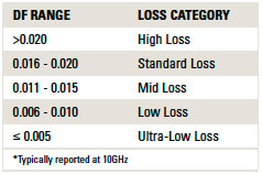
As mentioned last month, lower is better for Dk and Df. TABLE 1 shows how sophisticated users and manufacturers categorize laminates into five major Df groups, typically at 10GHz: high loss, standard loss, mid loss, low loss, and ultra-low loss. Note that precision for Df beyond three digits is usually artificial. Few have measurement equipment with that resolution.
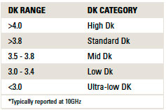
Less often, materials are categorized by dielectric constant. The most helpful groupings I’ve encountered are included in the left column of TABLE 2. Lower Dks mean narrower traces, thinner dielectrics, reduced crosstalk and lower total board thickness, typically at a slightly higher cost. Typical high-layer count, high-Tg laminates have dielectric constants in the 3.3 to 4.0 range.
The above categories can drive a much more refined perspective on the materials introduced in the April issue, as shown in FIGURE 2.
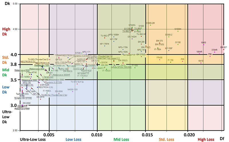
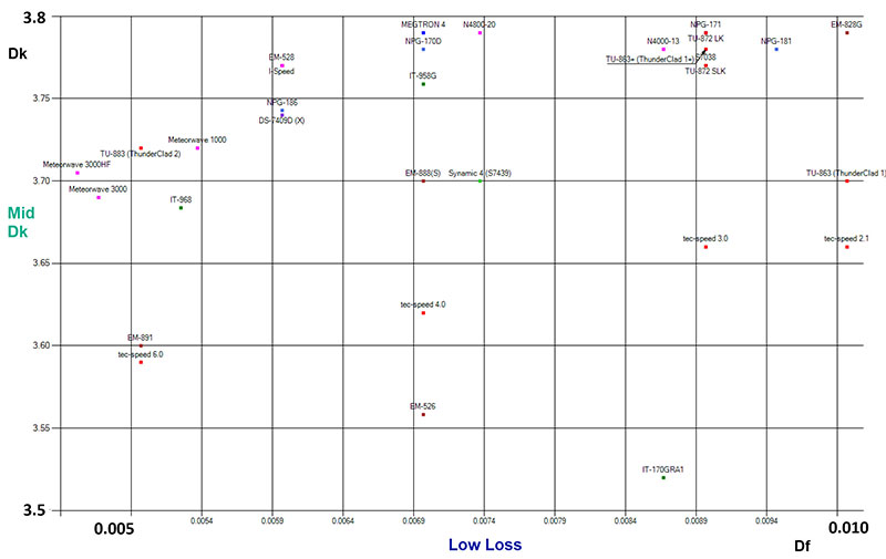
Application example. If designing a board in the 110-130 mil range, let’s say you want to consider materials with a Tg above 170°C in the “low loss” (Df ~0.005 to 0.010) and “mid Dk” (Dk ~3.5 to 3.8) range. That narrows the scope to the laminates in FIGURE 3.
So far, we’ve looked at Dk and Df. But we still have a pretty big list of possibilities. We’ll need additional selection heuristics to reach a conclusion. The options for selection criteria are broad as well. The shortlist could include price (of course), UL certification (sidebar), or a host of mechanical parameters. Signal-integrity simulation commonly narrows the scope of the materials to consider as well, depending on loss targets (Df) and crosstalk and board-thickness objectives (Dk).
Mechanical Parameters
It’s important to consider how different laminates may interact with the board design from a thermal- and mechanical-reliability standpoint. Many mechanical factors can be considered, including peel strength, moisture absorption, Young’s modulus, Poisson’s ratio, etc. Here we’ll discuss four thermal/mechanical parameters (including Tg), widely available from laminate datasheets, that can be employed to assess the interplay between board thickness, feature density, processing, and the interaction between a board design and the underlying dielectrics after exposure to multiple solder-reflow cycles. Before incorporating them into the decision process, let’s briefly define these parameters.
Glass-transition temperature (Tg): This is the temperature (in Celsius) at which deformation of a laminate changes dramatically. Tg values in the post-RoHS era range from 150°-260°C, measured in accordance with IPC-TM-650, method 2.4.24.3, 2.4.24c, or 2.4.25c.
Decomposition temperature (Td): This is the temperature (in Celsius) at which a material loses 5% of its weight as a result of thermal decomposition. Since the melting point of lead-free solder is around 225°C, solder-reflow temperatures during assembly and rework will be above 225°C, and as high as 260°C. Td values in the post-RoHS era range from 330°-430°C, measured in accordance with IPC-TM-650, method 2.3.40.
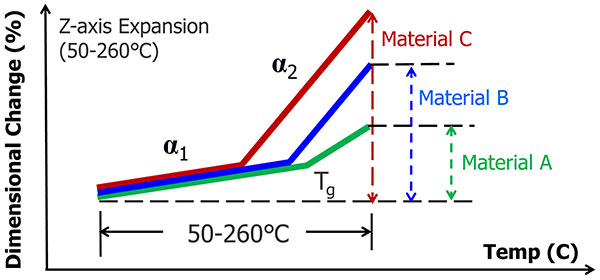
Z-axis expansion: One of the advantages of this figure of merit is it captures three different parameters in one number: z-CTE prior to Tg (alpha1), Tg (°C), and z-CTE after Tg (alpha2). FIGURE 4 shows this is measured as percent expansion, as a material temperature is raised from 50° to 260°C. Laminates expand much faster than copper with temperature, particularly after the glass-transition temperature, Tg. Prior to Tg (°C), laminates expand at a rate of around 50ppm/°C (known as alpha1) and after Tg, they expand at a rate of around 250ppm/°C (alpha2), depending on the specific resin system. The purpose is to assess a material’s susceptibility to heat-induced stresses in the z-direction that could lead to delamination. Values range from 1.3 to 3.5%, measured in accordance with IPC-TM-650, method 2.4.24.
X-y-CTE (coefficient of thermal expansion): The purpose of knowing a material’s x-y-CTE, measured from -40° to 125°C in ppm/°C, is to assess the degree to which a material’s x-y expansion will differ from the x-y expansion of BGA packages, with the goal of reducing solder joint failure. While BGA packages range from 5 to 8 ppm/°C, values for PCB laminates typically range from 10 to 16 ppm/°C. While it’s not the primary intent for this parameter, it can potentially be used to compare the degree to which feature registration may vary between dielectric materials during the lamination process, measured in accordance with IPC-TM-650, method 2.4.41.
The thicker the board, the greater the concern about stresses in the z-direction during soldering processes. Since boards are exposed to thermal excursions that exceed 225°C with today’s lead-free solder, PCB materials with the most severe thermal expansion are going to be a significant failure concern. The thicker the board, the more you’ll want to lean toward high Tg materials and materials with comparatively low z-CTEs.
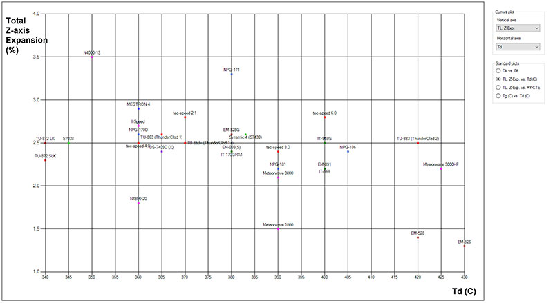
These additional parameters can shorten the list a bit more, before considering pricing and UL certification. Once the electrical solution space is established on thicker designs (more than 16 layers, for example), I like to analyze materials by comparing z-axis expansion to decomposition temperatures (FIGURE 5). The thicker the board, the more designers will want to concern themselves with these readily available datasheet parameters. From a reliability standpoint, materials in the bottom-right corner may perform somewhat better than other materials on the plot. This is not to say the other materials wouldn’t work. Arguably, z-axis expansion is more important than Td, as long as Td is greater than 260°C, a condition all these materials meet. Total board thickness, price and availability play roles too. All things being equal, including price and everything else, materials with lower z-axis expansion and higher Td would be worth considering on a board that’s 130 mils thick, for example.
Pricing
It wouldn’t surprise me to learn the laminates in the bottom-right quadrant were a bit more expensive than those in the top left. Simply stated, anything that improves laminate performance carries a higher cost. Anything, including but not limited to:
- Lower Dk
- Lower Df
- Reduced copper profile
- Low-Dk glass
- Lower halogen levels
- Lower CTE
- Higher Tg
- Higher thermal conductivity.
Some hardware engineers believe laminate pricing should be readily available, as if they were shopping on Amazon or buying resistors on DigiKey. The high-volume laminate industry didn’t evolve that way. The only things laminate vendors protect more closely than laminate and prepreg pricing are their chemical formulations and processes. Typically, price is discussed in a relative sense between Laminate A and Laminate B within the same vendor, and then detailed laminate pricing is quoted and negotiated with individual PCB fabricators on a volume basis and based on raw-material price fluctuations and competitive pressures.
As a rule of thumb, about one-third of the price of a bare PCB is comprised of the laminate itself. So, to understand the price delta between Laminate A and Laminate B is to have the PCB vendor quote the boards with each material. To further complicate things, a PCB fabricator will never break out the laminate component separately, so you won’t be able to tell if the laminate contribution is 32% or 38% of the total cost, and even if the laminate price can be somehow backwards-engineered at one PCB fabricator, that number won’t necessarily be valid at another vendor. A detailed quoting exercise at the board level is the only way to sort this out. Fortunately, once you’ve gone through this process, it should be reusable on future projects with the same material at the same fabricator – that is, until market factors drive changes in laminate prices again.
Parting Thoughts
Datasheet parameters cannot replace actual bench measurements in the lab or reliability testing on test vehicles that resemble production boards. Design teams that become proficient at making both electrical (i.e., Dk and Df) and thermal/mechanical (e.g., Tg, Td, z-axis expansion) tradeoffs from datasheet parameters when comparing laminates will be several steps ahead of design teams who just toss designs over the wall to fabricators for recommendations. Since stackup decisions and materials are the backbone of a board design, it would serve us all well to become savvier consumers, for electrical and mechanical reasons and cost control.